
Search FAQs
How do I access the Com Scanner Input and Output tables on the Altivar Process Drive?
Issue:
Access the Comm Scanner Input and Output tables on the Altivar Process Drive.
Product Line:
Altivar Process Drive (ATV630, ATV930, ATV650, ATV950, ATV660, ATV960, ATV680, ATV980)
Environment:
All serial numbers for Altivar Process Drive
Cause:
To configure the Comm. Scanner (Input/Output) tables:
Resolution:
Programming from the Drive:
Programming from Somove: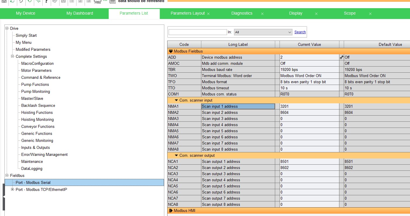
NOTE: This is not the same as the I/O scanning table that is used with Ethernet communications.
Access the Comm Scanner Input and Output tables on the Altivar Process Drive.
Product Line:
Altivar Process Drive (ATV630, ATV930, ATV650, ATV950, ATV660, ATV960, ATV680, ATV980)
Environment:
All serial numbers for Altivar Process Drive
Cause:
To configure the Comm. Scanner (Input/Output) tables:
Resolution:
Programming from the Drive:
- [Communication] [Comm parameters] [Modbus SL] [Modbus Fieldbus] [Com. scanner input]
- Up to 8 input registers can be configured
- By default the first 2 registers are pre-configured
- [Scan. IN1 address] nMA1 - 3201 (EtA Status word)
- [Scan. IN2 address] nMA2 - 8604 (rFrd - Output frequency)
- [Communication] [Comm parameters] [Modbus SL] [Modbus Fieldbus] [Com. scanner output]
- Up to 8 output registers can be configured
- By default the first 2 registers are pre-configured
- [Scan.Out1 address] nCA1 - 8501(CMd word)
- [Scan.Out2 address] nCA2 - 8602(LFrd - Output freq in rpm)
Programming from Somove:
- [Parameter List] [Fieldbus] [Port - Modbus Serial] [Modbus Fieldbus]
NOTE: This is not the same as the I/O scanning table that is used with Ethernet communications.
Released for:Schneider Electric India
Explore more
Explore more